Time: 2023-12-29 17:23:23View:
A Phase Locked Loop (PLL) is an electronic circuit that is widely used in various applications to synchronize the phase of an output signal with the phase of a reference signal. It is a control system that continuously adjusts the frequency and phase of the output signal to match that of the reference signal. The primary purpose of a PLL is to generate a stable and accurate output signal despite fluctuations or variations in the input or reference signal.
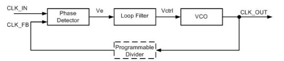
The basic components of a PLL include a phase detector (PD), a voltage-controlled oscillator (VCO), and a feedback loop. The phase detector compares the phase difference between the reference signal and the output signal and produces an error signal proportional to the phase difference. The error signal is then filtered and fed into the voltage-controlled oscillator, which generates an output signal with a frequency and phase that are adjusted according to the error signal.
The feedback loop in a PLL is responsible for continuously comparing the phase of the output signal with the reference signal and adjusting the VCO frequency accordingly to minimize the phase difference. As the phase difference decreases, the feedback loop reduces the error signal, causing the VCO to converge to the desired frequency and phase. This process continues until the output signal is locked in phase with the reference signal.
PLLs find applications in numerous fields, including telecommunications, data communication, frequency synthesis, clock recovery, and frequency modulation/demodulation. For example, in telecommunications, PLLs are used to recover the clock signal from a data stream or to generate a stable clock signal for timing purposes. In frequency synthesis, PLLs are utilized to generate signals with precise frequencies for applications such as wireless communication systems and frequency synthesizers.
One key advantage of PLLs is their ability to track and lock onto a varying reference signal, making them highly adaptable and suitable for applications where the input signal may experience frequency or phase variations. PLLs can provide excellent frequency stability, low phase noise, and fast acquisition times, making them essential in modern electronic systems.
In summary, a Phase Locked Loop is a versatile and powerful circuit that enables the synchronization of an output signal's phase with a reference signal. By continuously adjusting the frequency and phase of the output signal, PLLs provide stable and accurate signals despite variations in the input signal. They have a wide range of applications in various fields and are essential for ensuring reliable and precise operation in numerous electronic systems.
Phase Locked Loops (PLLs) operate based on a feedback control system that continuously compares the phase of an output signal with that of a reference signal and adjusts the output signal's frequency and phase to match the reference signal. This synchronization process involves several key stages.
The first stage of a PLL is the phase detector (PD), also known as a phase comparator or phase/frequency detector. The phase detector measures the phase difference between the reference signal and the output signal. It produces an error signal that represents the phase difference between the two signals. The error signal is proportional to the phase difference and is used to control the operation of the PLL.
The second stage is the loop filter. The error signal from the phase detector is typically a high-frequency signal. The loop filter is responsible for filtering and processing the error signal to obtain a low-frequency control voltage. The filtered voltage serves as the input to the voltage-controlled oscillator (VCO) in the next stage.
The VCO is a key component of the PLL. It generates an output signal whose frequency is controlled by the input voltage from the loop filter. The VCO's frequency is typically a multiple of the reference signal frequency and can be adjusted by changing the control voltage. The VCO's output signal is fed back to the phase detector, completing the feedback loop.
The feedback loop compares the phase of the output signal with that of the reference signal. If there is a phase difference, the phase detector produces an error signal that is then filtered and applied to the VCO, which adjusts its output frequency accordingly. The feedback loop continues to operate until the phase difference between the reference and output signals is minimized.
When the PLL is locked, the output signal is in phase and frequency synchronization with the reference signal. The loop filter and VCO work together to maintain the phase lock by continuously adjusting the output signal's frequency and phase. The loop filter helps to smooth out any fluctuations in the error signal and provides a stable control voltage to the VCO. The VCO responds to the control voltage by generating an output signal that tracks the reference signal closely.
PLLs offer several advantages in signal synchronization. They can track and lock onto a varying reference signal, providing stability and accuracy in the output signal. They also have the ability to suppress noise and interference, as the loop filter filters out high-frequency components. PLLs can achieve high-frequency stability, low phase noise, and fast acquisition times, making them versatile and widely used in various applications such as telecommunications, data communication, and frequency synthesis.
In summary, PLLs work by continuously comparing the phase of an output signal with that of a reference signal and adjusting the output signal's frequency and phase to achieve synchronization. The phase detector measures the phase difference, and the error signal is filtered to obtain a control voltage. The voltage-controlled oscillator generates an output signal whose frequency is controlled by the control voltage. The feedback loop continuously adjusts the output signal's frequency and phase until it is locked in phase with the reference signal. PLLs provide stable and accurate signals and find applications in numerous electronic systems.
Phase Locked Loops (PLLs) offer several advantages that make them widely used in various applications. One of the key advantages of PLLs is their ability to generate stable and precise clock signals. They can track and lock onto an input reference signal, providing frequency multiplication, division, and phase control. This makes PLLs invaluable in applications that require accurate timing, such as digital integrated circuits, microprocessors, and communication systems. PLLs help ensure synchronized operation and maintain the integrity of signals.
PLLs also offer excellent frequency stability. They can compensate for frequency variations due to temperature changes, manufacturing process variations, or aging effects. By continuously adjusting the output frequency to match the reference frequency, PLLs provide robust and reliable performance over time. This stability is crucial in applications that demand precise frequency control, including wireless communication, radar systems, and frequency synthesis.
Another advantage of PLLs is their ability to suppress phase noise. Phase noise can degrade the performance of communication systems, especially in high-speed data transmission. PLLs mitigate phase noise by tracking and filtering out frequency and phase variations, resulting in cleaner and more reliable signals. This is particularly important in applications that require high data rates, such as optical communication systems and high-speed data links.
PLLs also offer fast acquisition times, enabling rapid synchronization. Once locked onto the reference signal, PLLs can quickly align the output frequency and phase, reducing the time required for initial synchronization. This is beneficial in applications where fast startup and response times are critical, such as in data recovery circuits, synchronization of audio and video signals, and frequency hopping systems.
Despite their advantages, PLLs have a few limitations to consider. One drawback is their complexity. PLLs require additional components such as a phase detector, loop filter, and voltage-controlled oscillator (VCO). This complexity can increase the cost, power consumption, and design effort required for implementing a PLL-based system. Furthermore, the design and tuning of PLLs can be challenging, as they require careful consideration of loop stability, loop bandwidth, and filter characteristics to ensure proper performance.
Another limitation is the potential for jitter accumulation. Jitter refers to the short-term variations in the timing of a signal. Although PLLs can reduce and control jitter to some extent, they may introduce additional jitter due to noise and non-idealities in the system. This can be a concern in applications where precise time intervals or low jitter levels are critical, such as high-speed data communication or analog-to-digital conversion.
In summary, PLLs offer numerous advantages such as stable clock generation, frequency stability, phase noise suppression, and fast acquisition times. They are essential in applications that require accurate timing, synchronization, and reliable signal integrity. However, the complexity of PLLs and the potential for jitter accumulation should be carefully considered when designing and implementing PLL-based systems.
Phase Locked Loops (PLLs) have a wide range of applications across various industries where precise timing, synchronization, and frequency control are essential.
One of the primary applications of PLLs is in clock generation and distribution systems. PLLs are commonly used in microprocessors, digital signal processors (DSPs), and other digital integrated circuits to generate stable and accurate clock signals. These clock signals provide the necessary timing references for the proper operation of these devices. PLLs ensure that the generated clocks have low phase noise and maintain a precise frequency relationship with the input reference signal. This is crucial for maintaining the integrity and synchronization of digital systems.
PLLs are extensively utilized in frequency synthesis applications. They can generate high-frequency signals with precise frequency and phase relationships. This makes them critical in wireless communication systems, satellite communication, and radar applications. PLL-based frequency synthesizers are used to generate carrier frequencies, intermediate frequencies, and local oscillator signals in these systems. PLLs allow for precise frequency control, modulation, and demodulation, enabling reliable and accurate communication.
PLLs play a vital role in data recovery circuits. In high-speed data communication systems, such as fiber optic networks, Ethernet, or serial communication interfaces, PLLs are used to extract clock signals from incoming data streams. These PLL-based clock recovery circuits ensure accurate and reliable data retrieval by synchronizing with the incoming data and generating a clean and stable clock signal for proper sampling and decoding.
Audio and video applications also heavily rely on PLLs for synchronization purposes. PLLs are used in signal demodulation, audio/video processing, and broadcast systems. They help maintain synchronization between audio and video signals, ensuring smooth and accurate playback. PLLs are also utilized in digital audio systems, such as digital-to-analog converters (DACs), to generate precise clock signals for high-fidelity audio reproduction.
PLLs find extensive use in telecommunications systems. They are used in phase-locked loop synthesizers for wireless communication systems, enabling frequency hopping, modulation, and demodulation. PLLs are employed in clock recovery circuits in optical communication systems, where they extract timing information from received optical signals. They also play a crucial role in synchronization and timing recovery in telecommunication networks, helping to maintain accurate timing across multiple nodes and devices.
Additionally, PLLs are utilized in test and measurement instruments. Oscilloscopes, spectrum analyzers, and signal generators often incorporate PLLs to generate and synchronize signals for accurate measurements. PLLs provide stable and precise clock references to ensure reliable and precise measurements in a wide range of test and measurement applications.
In conclusion, PLLs have diverse applications across various industries. They are utilized in clock generation, frequency synthesis, data recovery, telecommunications, audio/video processing, and test and measurement instruments. PLLs enable precise timing, synchronization, and frequency control, ensuring the reliable and accurate operation of numerous electronic systems and communication networks.
