Time: 2025-02-10 14:43:56View:
Implementing an electronic clock using an FPGA (Field-Programmable Gate Array) is a great way to learn digital design and hardware description languages (HDLs) like VHDL or Verilog. Below is a step-by-step guide to designing and implementing a basic digital clock on an FPGA.

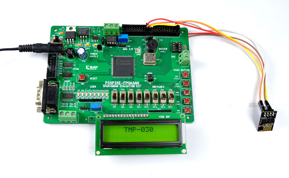
FPGA Development Board: Such as Xilinx Artix-7, Intel Cyclone, or any other FPGA board.
Clock Source: A stable clock signal (e.g., 50 MHz oscillator on the FPGA board).
Display: 7-segment displays or an LCD to show the time.
Inputs: Buttons or switches to set the time (hours, minutes, seconds).
HDL: VHDL or Verilog for coding the design.
The electronic clock will have the following components:
Clock Divider: Divides the high-frequency FPGA clock (e.g., 50 MHz) to a 1 Hz clock for seconds.
Time Counter: Counts seconds, minutes, and hours.
Time Setting Logic: Allows the user to set the time using buttons.
Display Driver: Converts the time into a format suitable for 7-segment displays or an LCD.
The FPGA clock is typically in the MHz range, but we need a 1 Hz clock for the seconds counter. Use a clock divider to generate a 1 Hz signal.
Verilog Example:
module clock_divider (
    input wire clk,       // 50 MHz clock
    input wire reset,     // Reset signal
    output reg clk_1hz    // 1 Hz clock);
    reg [25:0] counter;   // 26-bit counter for 50 MHz to 1 Hz

    always @(posedge clk or posedge reset) begin
        if (reset) begin
            counter <= 0;
            clk_1hz <= 0;
        end else begin
            if (counter == 26'd49_999_999) begin // 50 MHz / 50,000,000 = 1 Hz
                counter <= 0;
                clk_1hz <= ~clk_1hz; // Toggle 1 Hz clock
            end else begin
                counter <= counter + 1;
            end
        end
    endendmodule
Implement counters for seconds, minutes, and hours. Ensure the counters roll over correctly (e.g., 59 seconds → 0 seconds, 23 hours → 0 hours).
Verilog Example:
module time_counter (
    input wire clk_1hz,   // 1 Hz clock
    input wire reset,     // Reset signal
    output reg [5:0] seconds,
    output reg [5:0] minutes,
    output reg [4:0] hours);
    always @(posedge clk_1hz or posedge reset) begin
        if (reset) begin
            seconds <= 0;
            minutes <= 0;
            hours <= 0;
        end else begin
            if (seconds == 6'd59) begin
                seconds <= 0;
                if (minutes == 6'd59) begin
                    minutes <= 0;
                    if (hours == 5'd23) begin
                        hours <= 0;
                    end else begin
                        hours <= hours + 1;
                    end
                end else begin
                    minutes <= minutes + 1;
                end
            end else begin
                seconds <= seconds + 1;
            end
        end
    endendmodule
Add buttons to set the time. Use debouncing to avoid false triggers.
Verilog Example:
module time_setting (
    input wire clk,
    input wire reset,
    input wire set_hour,
    input wire set_minute,
    output reg [4:0] hours,
    output reg [5:0] minutes);
    always @(posedge clk or posedge reset) begin
        if (reset) begin
            hours <= 0;
            minutes <= 0;
        end else begin
            if (set_hour) begin
                if (hours == 5'd23) hours <= 0;
                else hours <= hours + 1;
            end
            if (set_minute) begin
                if (minutes == 6'd59) minutes <= 0;
                else minutes <= minutes + 1;
            end
        end
    endendmodule
Convert the binary time values into a format suitable for 7-segment displays or an LCD.
Verilog Example for 7-Segment Display:
module display_driver (
    input wire [5:0] seconds,
    input wire [5:0] minutes,
    input wire [4:0] hours,
    output reg [6:0] seg_hours_tens,
    output reg [6:0] seg_hours_ones,
    output reg [6:0] seg_minutes_tens,
    output reg [6:0] seg_minutes_ones,
    output reg [6:0] seg_seconds_tens,
    output reg [6:0] seg_seconds_ones);
    // Binary to 7-segment lookup table
    function [6:0] bin_to_seg;
        input [3:0] bin;
        begin
            case (bin)
                4'd0: bin_to_seg = 7'b1000000; // 0
                4'd1: bin_to_seg = 7'b1111001; // 1
                4'd2: bin_to_seg = 7'b0100100; // 2
                4'd3: bin_to_seg = 7'b0110000; // 3
                4'd4: bin_to_seg = 7'b0011001; // 4
                4'd5: bin_to_seg = 7'b0010010; // 5
                4'd6: bin_to_seg = 7'b0000010; // 6
                4'd7: bin_to_seg = 7'b1111000; // 7
                4'd8: bin_to_seg = 7'b0000000; // 8
                4'd9: bin_to_seg = 7'b0010000; // 9
                default: bin_to_seg = 7'b1111111; // Blank
            endcase
        end
    endfunction

    always @(*) begin
        seg_hours_tens = bin_to_seg(hours / 10);
        seg_hours_ones = bin_to_seg(hours % 10);
        seg_minutes_tens = bin_to_seg(minutes / 10);
        seg_minutes_ones = bin_to_seg(minutes % 10);
        seg_seconds_tens = bin_to_seg(seconds / 10);
        seg_seconds_ones = bin_to_seg(seconds % 10);
    endendmodule
Combine all the modules into a top-level module.
Verilog Example:
module electronic_clock (
    input wire clk,
    input wire reset,
    input wire set_hour,
    input wire set_minute,
    output [6:0] seg_hours_tens,
    output [6:0] seg_hours_ones,
    output [6:0] seg_minutes_tens,
    output [6:0] seg_minutes_ones,
    output [6:0] seg_seconds_tens,
    output [6:0] seg_seconds_ones);
    wire clk_1hz;
    wire [5:0] seconds;
    wire [5:0] minutes;
    wire [4:0] hours;

    clock_divider divider (.clk(clk), .reset(reset), .clk_1hz(clk_1hz));
    time_counter counter (.clk_1hz(clk_1hz), .reset(reset), .seconds(seconds), .minutes(minutes), .hours(hours));
    time_setting setting (.clk(clk), .reset(reset), .set_hour(set_hour), .set_minute(set_minute), .hours(hours), .minutes(minutes));
    display_driver driver (.seconds(seconds), .minutes(minutes), .hours(hours), .seg_hours_tens(seg_hours_tens), .seg_hours_ones(seg_hours_ones), .seg_minutes_tens(seg_minutes_tens), .seg_minutes_ones(seg_minutes_ones), .seg_seconds_tens(seg_seconds_tens), .seg_seconds_ones(seg_seconds_ones));endmodule
Simulate the design using tools like ModelSim or Vivado Simulator.
Program the FPGA and verify the functionality on the hardware.
Use onboard LEDs or a logic analyzer to debug signals.
Add an alarm feature.
Use an RTC (Real-Time Clock) module for more accurate timekeeping.
Display the time on an LCD instead of 7-segment displays.
By following these steps, you can successfully implement an electronic clock on an FPGA!