FPGA

An FPGA-based bunch-to-bunch feedback system at the Advanced Photon Source (APS)

Time: 2025-01-10 11:06:30View:

An FPGA-based bunch-to-bunch feedback system at the Advanced Photon Source (APS) is a sophisticated solution to mitigate instabilities in stored electron beams in synchrotron radiation facilities. These instabilities can degrade beam quality and affect the precision of experiments that rely on highly stable and well-defined photon beams.
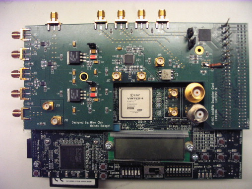
1-s2.0-S0168900208017890-gr3.jpg

Here’s an overview of how such a system functions and its key components:


Objective of the Feedback System

The primary goal of the system is to monitor and correct oscillations of individual electron bunches in real-time. These oscillations arise due to:

  1. Coupled-bunch instabilities, caused by wakefields generated in the storage ring.
  2. Resistive-wall effects, especially in high-current operations.
  3. Beam-loading effects or other impedance-related issues in the RF cavities.

By stabilizing these oscillations, the feedback system ensures:

  • Improved beam quality.
  • Reduced beam size and position jitter.
  • Consistent photon flux for experiments.

Why FPGA-Based?

Field-Programmable Gate Arrays (FPGAs) are ideal for real-time feedback systems because they offer:

  • High-speed data processing: Can handle the nanosecond-scale timing required for bunch-by-bunch feedback.
  • Parallel processing capabilities: Enables simultaneous monitoring and correction of multiple bunches.
  • Flexibility and programmability: Allows for customized algorithms and system updates.
  • Low latency: Essential for real-time corrections.

System Components

  1. Beam Position Monitors (BPMs):

    • Measure the position of each electron bunch as it passes through the storage ring.
    • Provide raw signal data (e.g., amplitude and phase) corresponding to bunch oscillations.
  2. Signal Processing Unit (FPGA):

    • Converts BPM signals into useful data (e.g., position and oscillation amplitude).
    • Runs custom feedback algorithms to determine corrective actions for each bunch.
    • Operates with nanosecond-level latency to handle bunch frequencies in the MHz range.
  3. Digital-to-Analog Converter (DAC):

    • Converts processed digital correction signals from the FPGA back into analog form for application to the beam.
  4. Corrector Kicker:

    • Applies precise electromagnetic kicks to individual bunches to correct their oscillations.
    • Operates in synchronization with the storage ring’s RF system to ensure bunch-specific targeting.
  5. Timing and Synchronization System:

    • Ensures all components operate in phase with the RF system of the storage ring.
    • Synchronizes with the bunch clock for accurate bunch targeting.
  6. User Interface and Data Logging:

    • Provides operators with real-time feedback on system performance.
    • Logs data for diagnostics and system tuning.

Operation Workflow

  1. Detection: BPMs pick up oscillation signals from individual bunches.
  2. Processing:
    • The FPGA processes these signals in real time to extract oscillation parameters.
    • Feedback algorithms compute the necessary correction for each bunch.
  3. Correction:
    • The DAC converts the correction signals.
    • The kicker applies the corrections to stabilize the oscillating bunches.
  4. Monitoring: System performance is continuously monitored, and adjustments are made as needed.

Challenges and Innovations

  1. Latency:

    • Minimizing latency is critical to ensure corrections are applied before oscillations grow.
    • FPGA parallel processing and optimized hardware architectures address this challenge.
  2. High Bunch Frequencies:

    • APS storage rings typically operate at RF frequencies in the range of hundreds of MHz.
    • The FPGA must handle data rates corresponding to these high frequencies.
  3. Customization and Scalability:

    • The system must adapt to various beam configurations and storage ring upgrades.
    • Modular FPGA designs allow for future scalability.
  4. Integration with APS:

    • Seamless integration with the existing APS infrastructure, including RF systems and control networks, is essential.

Benefits for the Advanced Photon Source

  • Enhanced Stability: Maintains beam stability even at higher currents and challenging operational regimes.
  • Improved Beam Quality: Delivers higher brightness and coherence for synchrotron radiation experiments.
  • Increased Operational Flexibility: Supports diverse experimental setups with varying beam requirements.
  • Future Proofing: FPGA systems are reconfigurable, making them suitable for upgrades and expansions.

This system exemplifies the role of advanced electronics and real-time processing in pushing the boundaries of synchrotron science.