FPGA

How to achieve wireless communication between two FPGA development boards?

Time: 2025-02-05 15:15:05View:

Achieving wireless communication between two FPGA development boards requires integrating a wireless module or transceiver that can interface with the FPGA. Here’s a step-by-step guide:

ASKModules.jpg

1. Choose a Wireless Communication Protocol

Depending on the application requirements (range, data rate, power consumption), you can select from the following wireless protocols:

  • Wi-Fi (ESP8266, ESP32, WIZ610wi, etc.) – Good for high-speed data transmission and internet connectivity.
  • Bluetooth (HC-05, HC-06, or BLE modules like NRF24L01) – Suitable for short-range communication.
  • LoRa (SX1278, RFM95) – Great for long-range, low-power applications.
  • Zigbee (XBee Series) – Suitable for mesh networking.
  • RF Transceivers (NRF24L01, CC1101, etc.) – Simple and effective for short-range wireless communication.

2. Select a Compatible Wireless Module

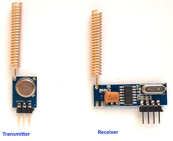
FPGA boards typically do not have built-in wireless capabilities, so an external module must be used. Common choices include:

  • NRF24L01 (SPI-based)
  • ESP8266/ESP32 (UART/SPI)
  • LoRa SX1278 (SPI)
  • XBee (UART-based)

3. Interface the Wireless Module with FPGA

Since most wireless modules use SPI, UART, or I2C, you need to implement these communication protocols in your FPGA using Verilog or VHDL. Here’s how:

SPI Communication (for NRF24L01, LoRa)

  1. Implement an SPI master module in the FPGA.
  2. Connect the SPI signals (MOSI, MISO, SCK, CSN) to the wireless module.
  3. Write a state machine to send/receive data packets.

UART Communication (for XBee, ESP8266)

  1. Implement a UART transmitter and receiver in FPGA.
  2. Connect TX/RX pins to the wireless module.
  3. Send AT commands (if required) to configure the module.

4. Develop the FPGA Firmware

  • Implement logic to send and receive data.
  • If using a transceiver like NRF24L01, set up a state machine to configure the module, transmit, and receive packets.
  • For ESP8266/ESP32, send AT commands via UART to establish communication.

5. Power and Signal Considerations

  • Some modules operate at 3.3V (NRF24L01, ESP8266, XBee) while FPGAs might use 1.8V or 2.5V logic levels. Use level shifters if necessary.
  • Ensure proper grounding and decoupling capacitors to reduce noise.

6. Test and Debug

  • Use a logic analyzer to verify SPI/UART signals.
  • Check for successful data transmission using an oscilloscope or serial terminal.
  • Implement a handshake mechanism to confirm data integrity.

Example Setup

If using NRF24L01, the FPGA SPI master sends data packets to another FPGA via the transceiver. The receiving FPGA extracts the data and processes it.