Time: 2025-02-12 11:25:15View:
Creating a music player using an FPGA (Field-Programmable Gate Array) is an exciting project that combines digital logic design, signal processing, and audio playback. Below is a step-by-step guide to help you design and implement a basic music player using an FPGA:
The goal is to create a music player that can:
Read audio data from a storage medium (e.g., SD card or flash memory).
Decode the audio file (e.g., WAV or MP3).
Process the audio signal using a Digital Signal Processing (DSP) pipeline.
Output the audio to a speaker or headphones via a Digital-to-Analog Converter (DAC).
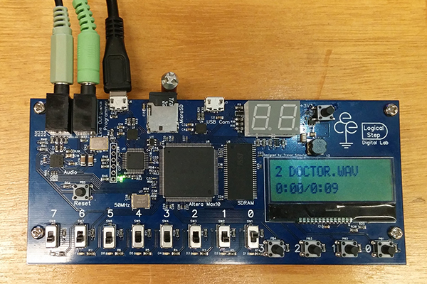
FPGA Development Board: Such as Xilinx Zynq, Intel (Altera) Cyclone, or Lattice iCE40.
Storage Medium: SD card or flash memory to store audio files.
Audio Codec/DAC: For converting digital audio signals to analog (e.g., PCM5102, WM8731).
Speaker/Headphones: For audio output.
Buttons/Switches: For controlling playback (play, pause, next, previous).
Display (Optional): LCD or OLED to show track information.
Storage Interface: Implement an SD card or flash memory controller to read audio files.
File Decoder: Design or use an IP core to decode audio files (e.g., WAV or MP3).
Audio Processing: Implement a DSP pipeline for volume control, equalization, or effects.
DAC Interface: Generate the necessary signals (e.g., I2S or PWM) to interface with the audio DAC.
Control Logic: Handle user inputs (play, pause, etc.) and manage the overall system.
Use an SPI or SDIO interface to read audio files from the SD card.
Store the audio data in a buffer (e.g., block RAM or external SDRAM).
For WAV files: The format is uncompressed, so you only need to parse the header and extract the raw PCM data.
For MP3 files: Use an open-source MP3 decoder IP core or implement your own decoder (requires significant DSP knowledge).
Implement a DSP pipeline to process the audio signal:
Volume control: Multiply the audio samples by a gain factor.
Equalization: Apply filters to adjust frequency response.
Effects: Add reverb, echo, or other effects (optional).
Use an I2S or PWM interface to send digital audio data to the DAC.
I2S is commonly used for high-quality audio, while PWM is simpler but lower quality.
Design a finite state machine (FSM) to handle user inputs (play, pause, next, previous).
Optionally, add a display to show the current track and playback status.
Use FPGA development tools like Xilinx Vivado, Intel Quartus, or Lattice Diamond.
Write your design in Verilog or VHDL.
1. SD Card Reader:
Implement SPI communication to read audio files.
Parse the file system (e.g., FAT16/FAT32) to locate the audio file.
2. Audio Decoder:
For WAV files: Extract PCM data from the file.
For MP3 files: Use an IP core or implement a decoder.
3. DSP Pipeline:
Apply volume control, filtering, or effects to the audio data.
4. I2S/PWM Interface:
Generate the clock, data, and control signals for the DAC.
5. Control Logic:
Handle user inputs and manage playback.
Simulate each module using a testbench.
Verify the functionality of the SD card interface, audio decoder, and DSP pipeline.
Test the audio output with a DAC and speaker.
module i2s_transmitter (
    input wire clk,
    input wire reset,
    input wire [15:0] audio_data,
    output reg i2s_sck,
    output reg i2s_ws,
    output reg i2s_sd);
    reg [15:0] shift_reg;
    reg [4:0] bit_count;

    always @(posedge clk or posedge reset) begin
        if (reset) begin
            shift_reg <= 16'b0;
            bit_count <= 5'b0;
            i2s_sck <= 1'b0;
            i2s_ws <= 1'b0;
            i2s_sd <= 1'b0;
        end else begin
            i2s_sck <= ~i2s_sck;
            if (i2s_sck) begin
                if (bit_count == 5'd15) begin
                    shift_reg <= audio_data;
                    bit_count <= 5'b0;
                    i2s_ws <= ~i2s_ws;
                end else begin
                    shift_reg <= {shift_reg[14:0], 1'b0};
                    bit_count <= bit_count + 1;
                end
                i2s_sd <= shift_reg[15];
            end
        end
endendmoduleAdd support for multiple audio formats (e.g., MP3, FLAC, AAC).
Implement a graphical user interface (GUI) on an LCD or OLED display.
Add wireless connectivity (e.g., Bluetooth) for remote control.
This project is a great way to learn about FPGA design, digital signal processing, and embedded systems.
