Time: 2025-03-11 11:53:50View:
Designing and implementing an automatic driving control system for a small car using an FPGA is a complex but fascinating project. FPGAs are ideal for such applications due to their parallel processing capabilities, real-time performance, and flexibility. Below is a detailed guide to designing and implementing this system:
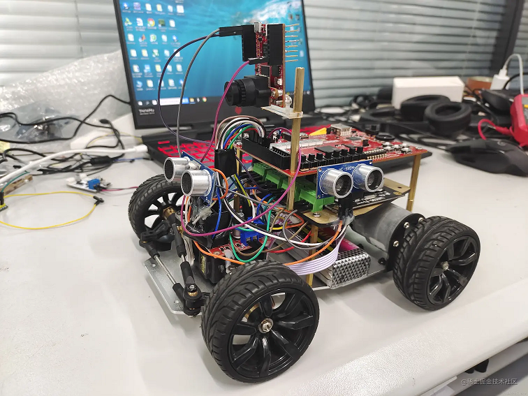
The automatic driving control system will enable a small car to navigate autonomously by processing sensor data, making decisions, and controlling the car's motors. The system will include the following components:
1. Sensors:
Ultrasonic sensors or LiDAR for obstacle detection.
Infrared (IR) sensors or camera for line following or object detection.
IMU (Inertial Measurement Unit) for orientation and acceleration data.
2. FPGA:
The FPGA will process sensor data, implement control algorithms, and generate motor control signals.
3. Motor Drivers:
Control the car's wheels using PWM signals from the FPGA.
4. Communication Interface:
UART, SPI, or I2C for communication between sensors, FPGA, and other peripherals.
5. Power Supply:
Provide stable power to the FPGA, sensors, and motors.
The system can be divided into the following modules:
1. Sensor Interface:
Read data from ultrasonic sensors, IR sensors, cameras, and IMU.
2. Data Processing:
Process sensor data to detect obstacles, follow lines, or navigate.
3. Control Algorithm:
Implement algorithms for decision-making (e.g., obstacle avoidance, path planning).
4. Motor Control:
Generate PWM signals to control the car's motors.
5. User Interface (Optional):
Add a display or Bluetooth module for status monitoring and control.
Determine the car's functionality (e.g., line following, obstacle avoidance, autonomous navigation).
Choose appropriate sensors and actuators.
Choose an FPGA board with sufficient resources (e.g., Xilinx Zynq, Intel Cyclone, or Lattice ECP5).
Ensure the board has GPIOs for sensor interfacing and PWM outputs for motor control.
Ultrasonic Sensors:
Use a timer module to measure the time of flight for distance calculation.
IR Sensors:
Read analog or digital signals to detect lines or obstacles.
Camera:
Use an image processing module to detect lanes or objects.
IMU:
Read accelerometer, gyroscope, and magnetometer data for orientation.
Obstacle Detection:
Use sensor data to detect obstacles and calculate distances.
Line Following:
Process IR sensor or camera data to follow a line.
Path Planning:
Implement algorithms (e.g., A* or Dijkstra) for navigation.
Use a state machine or decision-making logic to control the car's behavior.
Example:
If an obstacle is detected, steer away.
If the car deviates from the line, adjust the steering.
Generate PWM signals to control the speed and direction of the motors.
Use an H-bridge motor driver to interface with the motors.
Combine all modules and test the system.
Verify the car's ability to navigate autonomously.
Xilinx Zynq-7000 FPGA board with GPIOs and PWM outputs.
Ultrasonic sensors for obstacle detection.
IR sensors for line following.
IMU for orientation data.
1. Sensor Interface:
Read data from ultrasonic sensors, IR sensors, and IMU.
2. Data Processing:
Calculate distances from ultrasonic sensors.
Detect lines using IR sensors.
3. Control Algorithm:
Implement a state machine for obstacle avoidance and line following.
4. Motor Control:
Generate PWM signals for motor control.
FPGA Design Tools:
Xilinx Vivado (for Xilinx FPGAs)
Intel Quartus (for Intel FPGAs)
Lattice Diamond (for Lattice FPGAs)
Programming Languages:
Use Verilog or VHDL for hardware design.
Use C/C++ for soft-core processors (e.g., MicroBlaze or Nios II) if needed.
IP Cores:
Use pre-built IP cores for sensor interfacing, PWM generation, and communication protocols (e.g., UART, SPI, I2C).
1. Real-Time Processing:
Ensure the FPGA can process sensor data and generate control signals in real time.
2. Sensor Integration:
Calibrate and synchronize data from multiple sensors.
3. Power Management:
Provide stable power to the FPGA, sensors, and motors.
4. Algorithm Complexity:
Optimize control algorithms for efficient hardware implementation.
Designing and implementing an automatic driving control system for a small car using an FPGA is a challenging but rewarding project. By leveraging the FPGA's parallel processing capabilities, you can create a high-performance, real-time control system. Start with basic functionality (e.g., line following or obstacle avoidance) and gradually add advanced features (e.g., path planning, object detection). This project provides an excellent opportunity to explore embedded systems, digital design, and autonomous vehicle technologies.
