Time: 2025-06-03 11:18:53View:
This document outlines the design of an infrared (IR) remote control system implemented on a Field Programmable Gate Array (FPGA). The system can both transmit and receive IR signals compatible with common remote control protocols like NEC, RC5, or Sony SIRC.
The IR remote control system consists of two main components:
IR Transmitter: Encodes and transmits commands via infrared LED
IR Receiver: Decodes incoming infrared signals from remote controls
[FPGA]
   |
   |-- IR Transmitter Module
   |     |-- Command Encoder
   |     |-- Modulation Unit (38kHz carrier)
   |     └-- IR LED Driver
   |
   └-- IR Receiver Module
         |-- IR Sensor Interface
         |-- Demodulation Unit
         └-- Command Decoder
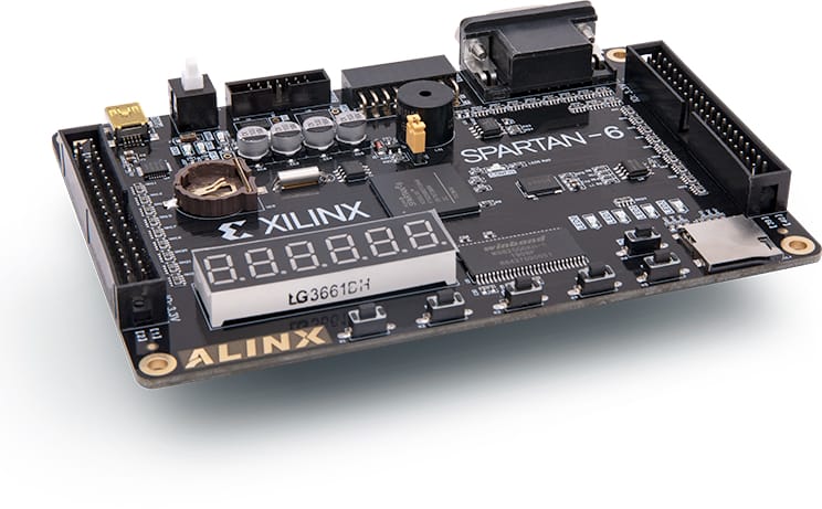
FPGA development board
Infrared LED (e.g., TSAL6200)
NPN transistor (for LED driving, e.g., 2N2222)
Current-limiting resistor (typically 100Ω)
IR receiver module (e.g., TSOP1738, VS1838B)
Optional signal conditioning circuitry
entity ir_encoder is
    port (
        clk      : in  std_logic;
        reset    : in  std_logic;
        command  : in  std_logic_vector(7 downto 0);
        ir_out   : out std_logic    );end ir_encoder;
Implements the specific protocol encoding (NEC shown here):
9ms leading pulse burst
4.5ms space
8-bit address + 8-bit command (LSB first)
Each bit: 560µs pulse + 560µs space (0) or 1.68ms space (1)
Generates 38kHz carrier signal (26.3µs period):
process(clk)begin
    if rising_edge(clk) then
        if counter < carrier_half_period then
            carrier <= not carrier;
            counter <= 0;
        else
            counter <= counter + 1;
        end if;
    end if;end process;
entity ir_receiver is
    port (
        clk          : in  std_logic;
        reset        : in  std_logic;
        ir_input     : in  std_logic;
        data_valid   : out std_logic;
        command_out  : out std_logic_vector(7 downto 0)
    );end ir_receiver;
State machine implementation for decoding:
Detect start pulse
Measure pulse/space durations
Decode address and command bits
Validate checksum (if applicable)
Output valid command
Critical timing parameters for NEC protocol:
Start pulse: 9ms ±10%
Start space: 4.5ms ±10%
Bit 0: 560µs pulse + 560µs space
Bit 1: 560µs pulse + 1.68ms space
Repeat code: 9ms pulse + 2.25ms space
Estimated resource usage for Xilinx Spartan-6:
Transmitter: ~50 slices
Receiver: ~100 slices
Total design: ~150 slices (less than 10% of XC6SLX9)
IR transmitter simulation with protocol compliance
IR receiver response to valid/invalid signals
End-to-end command transmission/reception
Range testing (typical 5-10 meters)
Angle sensitivity testing
Noise immunity testing
Home automation control
Consumer electronics remote
Industrial equipment control
Educational demonstration platform
Multi-protocol Support: Add detection/selection of different IR protocols
Learning Mode: Capture and store codes from existing remotes
Wireless Bridge: Convert IR commands to RF or network packets
Macro Support: Store and execute command sequences
This FPGA-based IR remote control system provides a flexible platform for implementing infrared communication with configurable protocols and excellent timing accuracy. The design can be adapted for various applications requiring remote control functionality.
