Time: 2025-04-08 11:20:40View:
This design outlines a real-time target tracking electromagnetic (coilgun/railgun) system using an FPGA for high-speed processing, combined with sensors, actuators, and control algorithms.
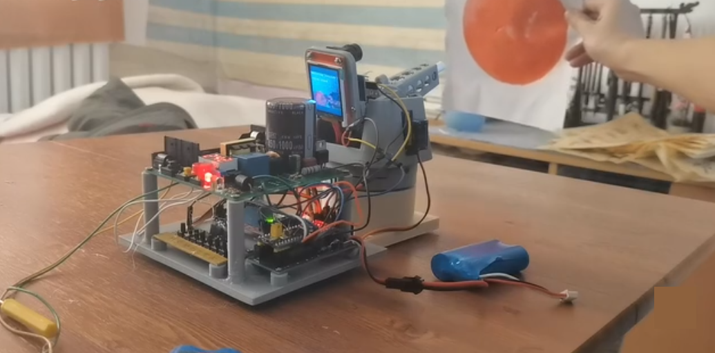
The system consists of:
FPGA (Xilinx Zynq or Intel Cyclone) for real-time processing.
Target Tracking (Camera + IMU + Lidar).
Electromagnetic Coilgun/Railgun (Pulsed power driver).
Control System (PID for aiming, firing timing).
Power Supply (High-voltage capacitors, MOSFET drivers).
| FPGA | Key Features |
|---|---|
| Xilinx Zynq-7000 | ARM Cortex + FPGA, good for sensor fusion. |
| Intel Cyclone V | Low-latency processing, high-speed I/O. |
| Lattice ECP5 | Low-power, cost-effective for simpler designs. |
| Sensor | Purpose |
|---|---|
| CMOS Camera (OV7670, IMX219) | Visual tracking (OpenCV/FPGA-based edge detection). |
| IMU (MPU6050, BNO085) | Target motion prediction (accelerometer + gyro). |
| LIDAR (TFMini, VL53L0X) | Distance measurement for firing timing. |
| Component | Function |
|---|---|
| High-Voltage Capacitors (400V, 1000µF) | Energy storage for coilgun. |
| MOSFET/IGBT Array (IRFP460, STGP30NC60WD) | Fast switching for coil activation. |
| Gate Driver (IR2110, TC4420) | Isolated MOSFET triggering. |
| Module | Role |
|---|---|
| Stepper/Servo Motors | Adjust gun barrel direction. |
| Optical Encoder | Feedback for barrel position. |
Camera Interface (OV7670 I2C/Parallel) → Edge detection (Sobel filter in FPGA).
IMU Data Processing (Kalman Filter for motion prediction).
LIDAR Distance Calculation (Time-of-flight measurement).
PWM Generation for coil activation timing.
PID Control (for motorized aiming).
Safety Interlock (Prevents firing without target lock).
// Example: FPGA-based coil triggeringmodule Coil_Trigger (
  input clk, target_locked,
  output reg coil_pulse);
  always @(posedge clk) begin
    if (target_locked) begin
      coil_pulse <= 1'b1; // Activate MOSFET driver
      #100;               // Pulse width control
      coil_pulse <= 1'b0;
    end
  endendmodule
Capacitor Bank Charging Circuit (Boost converter + flyback transformer).
Safe Discharge Mechanism (Bleeder resistors, relay cutoff).
FPGA Power Isolation (LDOs + Ferrite beads for noise immunity).
FPGA Firmware (VHDL/Verilog for real-time control).
Microcontroller Co-Processing (ARM Cortex for trajectory math).
Machine Learning (Optional) – Neural networks for predictive aiming.
Static Target Test (Adjust PWM for optimal coil timing).
Dynamic Tracking Test (Validate IMU + camera fusion).
Energy Efficiency Check (Capacitor recharge rate vs. firing frequency).
Optical Isolation (Prevents high-voltage feedback to FPGA).
Manual Override (Emergency stop button).
Current Limiting (Prevents coil overheating).
Multi-Coil Staging (For higher projectile velocity).
Wireless Remote Control (ESP32/Wi-Fi link).
Automated Reload Mechanism (For continuous firing).
This FPGA-based electromagnetic gun system combines real-time tracking, high-speed control, and pulsed power electronics for precise target engagement. The FPGA ensures low-latency processing, while sensor fusion improves accuracy.
Next Steps:
Prototype with a single-stage coilgun.
Optimize tracking algorithms in HDL.
Test different capacitor configurations for max energy transfer.
